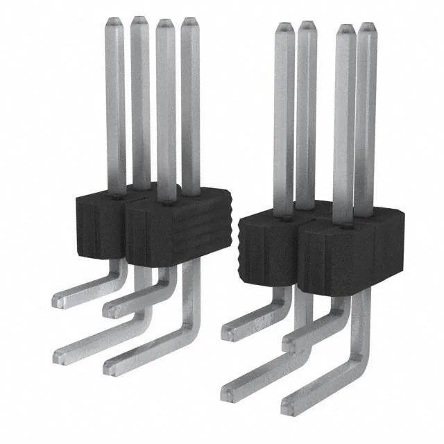
Rated 5 A per contact with tin-on-tin mating surfaces (100.0 µin / 2.54 µm on the pin side). The 5 A figure is typical for signal-level duty at this pitch; the tin plating keeps cost down for moderate-cycle applications where the connector mates a handful of times over its life.
Board Layout and Footprint
The 0.100" row spacing matches the standard 0.100" pitch between rows, so the 42-pin footprint occupies a 21-pin-per-row grid. The mating pin length is 0.318" (8.08 mm) and the post length is 0.110" (2.79 mm) — the post is short, meant for a single-sided PCB where the solder tail does not protrude far past the board. Insulation height is 0.240" (6.10 mm) above the board surface.
Termination is solder to through-hole; the square pins are 0.025" square, compatible with wire-wrap posts or standard crimp terminals.
No official cross-reference or replacement is on record, so the BOM line should match this exact order code.