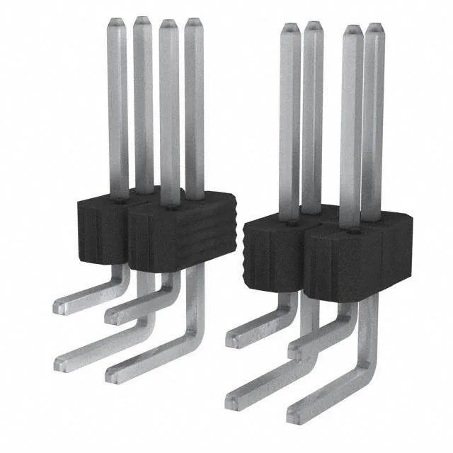
Rated at 5 A per circuit with a 110 V voltage ceiling, and built with a UL94 V-0-rated black housing, it is designed for internal board-stacking or cable-to-board signal duty where the mating half is an unshrouded receptacle or a shrouded header with matching 0.100" pitch.
The 0.100" (2.54 mm) pitch and 0.100" row spacing define the board footprint — standard 0.100" grid, no custom pad layout needed. The 44 positions across two rows means the header occupies 22 positions per row, so the PCB footprint is a 2x22 pattern with 0.100" between centres. The contact finish is tin on both the mating surface and the solder tail — 100.0 µ" (2.54 µm) on the mating side is a thick tin layer, but tin-on-tin contacts are rated for a limited number of mating cycles (typically 25–50 mates) and are susceptible to fretting corrosion under vibration. This is a one-time-assembly or low-cycle interconnect, not a field-service disconnect. The right-angle through-hole termination gives a solder tail length of 0.110" (2.79 mm) for the PCB hole depth, and the mating pin length of 0.318" (8.08 mm) provides enough reach to engage a standard 0.100" pitch receptacle.