The 77311-119-05LF: Termination is solder-only (through hole). The contact material is phosphor bronze, chosen for spring retention and corrosion resistance. The post finish is tin (78.7 µinch), compatible with lead-free soldering processes.
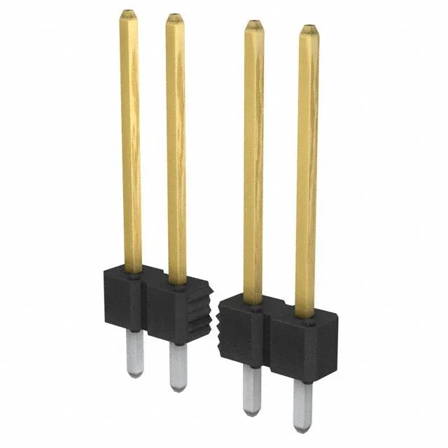
77311-119-05LF BERGSTIK® 5-Pin Header 2.54mm Pitch
MPN77311-119-05LF
Active
Amphenol ICC (FCI) BERGSTIK® series, 77311-119-05LF, unshrouded male pin header, 5 positions, single row, 0.100" (2.54 mm) pitch, through-hole solder termination, 3 A per contact, gold or GXT™ mating finish.
$0.8600Ref. price · indicative, final on quote
RoHSRoHS Compliant
SeriesBERGSTIK®
Source DocumentedChannel stated on listing & quote
Condition PhotosReal unit photos / video on request
WhatsApp AnswersFast human replies for stock & sourcing questions
Worldwide DispatchDHL/FedEx — transit quoted per order
Independent China distributor & sourcing agent· Listing updated Aug 2026
Specifications
| Parameter | Value |
|---|---|
| Series | BERGSTIK® |
| Type | Male Pin |
| Mounting | Through Hole |
| Connector type | Header |
| Fastening type | Push-Pull |
| Current rating | 3A per Contact |
| Operating temperature | -65°C~125°C |
| Contact material | Phosphor Bronze |
| Insulation color | Black |
| Insulation height | 0.100\" (2.54mm) |
| Insulation material | Thermoplastic |
| Material flammability rating | UL94 V-0 |
All specifications
| Parameter | Value |
|---|---|
| Style | Board to Board |
| Package | Bulk |
| Shrouding | Unshrouded |
| Termination | Solder |
| Contact shape | Square |
| Rows | 1 |
| Pitch | 0.100\" (2.54mm) |
| Positions | 5 |
| Contact finish - post | Tin |
| Contact length - post | 0.119\" (3.02mm) |
| Overall contact length | 0.724\" (18.40mm) |
| Contact finish - mating | Gold or Gold, GXT™ |
| Contact length - mating | 0.505\" (12.83mm) |
| Contact finish thickness - post | 78.7µin (2.00µm) |
| Contact finish thickness - mating | 30.0µin (0.76µm) |
Product details
Frequently asked questions
What is the pinout of the 77311-119-05LF?
It is a single-row, 5-position header with all positions loaded. Pin 1 is typically marked by a square pad on the PCB footprint; the remaining pins follow sequentially along the row.