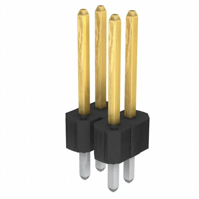
What the 4-Pin Dual-Row Layout Buys You
The 78548-204HLF: The 0.100" row spacing matches the column pitch, so the pin grid is a square 2×2 array that drops onto standard perfboard or 0.100" grid prototyping boards without a custom footprint.
How It Stacks Against Siblings
The closest functional peer is 69192-202HLF — same dual-row, 0.100" pitch, 15 µinch gold finish, but only 2 positions (single pair). If the BOM calls for 4 circuits, 78548-204HLF is the correct pick; the 2-position part leaves two pads empty. For applications that need higher mating cycle life, 68491-104HLF carries 30.0 µinch gold (double the thickness) at the same 4-position, 0.100" pitch layout. The thicker gold raises the cycle rating but the footprint and pinout are identical — a drop-in swap if the budget allows. The 72-position sibling 67997-272HLF shares the same plating and pitch but is a different part entirely for high-density backplane use — not a cross-shop for a 4-circuit BOM line.
Kinked-pin solder termination — the kink in the post provides a press-fit retention in the plated through-hole before wave soldering, holding the header in place during assembly. Plan the z-height budget accordingly.