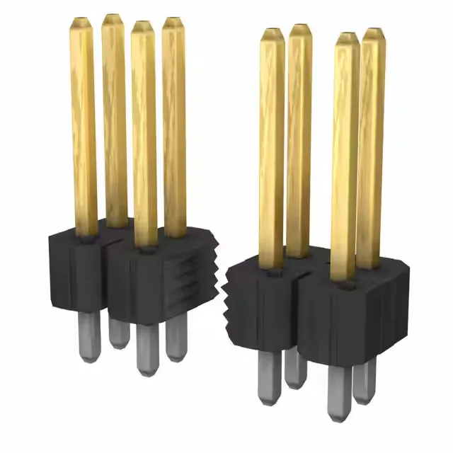
It uses the industry-standard 0.100" (2.54mm) pitch on both the pin-to-pin and row spacing, which means it drops onto a standard 0.100" grid footprint — the same layout used by legacy ribbon-cable IDC connectors and general-purpose protoboard. Rated 5 A per circuit at 110 V, with gold or Gold GXT™ plating at 30.0 µin (0.76 µm) on the mating surface. The 30.0 µ" gold layer gives enough corrosion resistance for production assemblies that see occasional rework or field service, but it is not spec'd for daily disconnect cycles. This is a common configuration for board-to-board stacking where the mated pair is held in place by the board assembly hardware, not the connector latch.
Position count and footprint
68 circuits in a dual-row layout at 0.100" pitch means the header occupies a 34-position-per-row footprint, roughly 3.4" long plus the 0.100" insulation height above the board. The overall contact length is 0.525" (13.34mm), split into a 0.325" (8.26mm) mating tail and a 0.100" (2.54mm) solder post. The short 0.100" post is a through-hole design for standard 0.062" PCBs — it does not extend far enough for thick backplane boards.