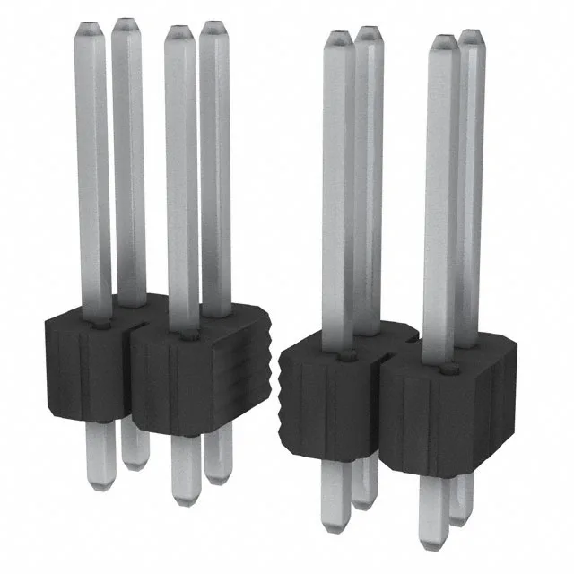
It uses a 0.100" (2.54 mm) square grid on both the row and pin spacing, which is the standard footprint for legacy through-hole board-to-board interconnects.
Rated 5 A per contact at 110 V, the current capacity is typical for a 0.100" pitch header with tin-plated contacts — the limiting factor is the temperature rise in the housing rather than the contact itself. The 100.0 µin (2.54 µm) tin plating on the mating surface is a thick industrial-grade finish suited for a moderate number of mating cycles in a clean environment; it is not a high-cycle gold replacement. Through-hole solder termination with a 0.100" (2.54 mm) post length suits standard 0.062" to 0.093" PCBs. The overall contact length of 0.525" (13.34 mm) and a mating length of 0.325" (8.26 mm) are dimensions to check against your mating receptacle's insulation height — the BERGSTIK II receptacle's shroud depth determines how far the pins insert.
Board layout note
The 0.100" (2.54 mm) pitch and 0.100" (2.54 mm) row spacing define a standard 0.100" x 0.100" grid. The footprint is a 2 x 6 array of 0.040" diameter plated-through holes on that grid. The unshrouded header has no plastic wall around the pins, so the keep-out zone on the PCB is minimal — just the hole pattern and the body outline at 0.100" (2.54 mm) insulation height above the board.