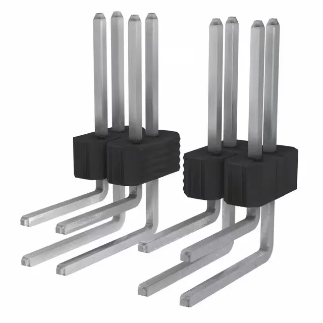
It uses the industry-standard 0.100" (2.54 mm) pitch on both rows and between rows, making it footprint-compatible with legacy DIP-style grid layouts and common 0.100" ribbon cable receptacles. The 100.0 µ" (2.54 µm) tin plating on the mating surface is a heavy tin deposit — thicker than the typical 30-50 µ" flash — giving it better wear resistance than a light tin plate, though still best suited for applications with a limited number of mating cycles. Phosphor bronze contacts provide a reliable spring beam with good fatigue life. All 18 positions are loaded — no empty pin locations to track on the BOM.
Right-angle board placement
With a mating pin length of 0.318" (8.08 mm) and a post length of 0.230" (5.84 mm), the header stands 0.190" (4.83 mm) above the board surface at the insulator.