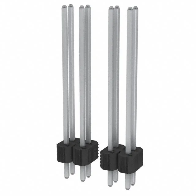
The 0.100" x 0.100" grid is the bread-and-butter of through-hole PCB design — the footprint is a standard 0.025" square pin in a 0.040" plated hole, and the 0.100" pitch leaves enough room for one trace between pads on a single-layer board. The 56 positions, all loaded, give you a 28-pin-per-row density that suits wide parallel data buses or dense I/O banks. The overall contact length of 1.040" (26.42 mm) breaks down into a 0.820" mating tail and a 0.120" solder post — the long mating pin is designed to reach through a mating receptacle and still give good wipe, while the short post keeps the through-hole solder joint compact on the back side of the board.
Deployment Context
The unshrouded header and UL94 V-0 rated black thermoplastic housing suit it for internal board-to-board connections inside equipment enclosures where the connector won't see casual handling or cable strain. The push-pull retention means the mating receptacle needs its own locking feature if vibration is a concern — this header relies entirely on the friction of the pin-receptacle interface.