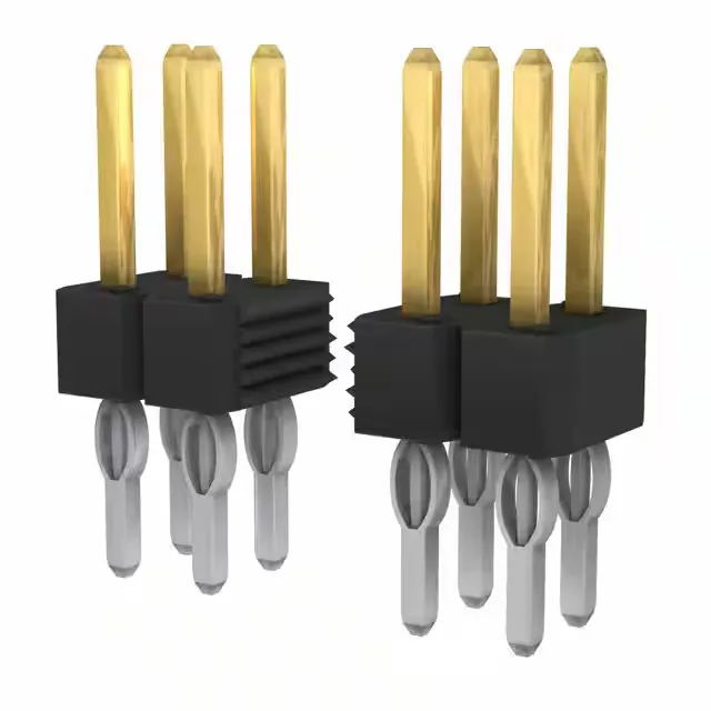
It uses a 0.100" (2.54mm) square-pin grid on two rows with the same 0.100" row spacing, giving a standard footprint that matches legacy 0.100" ribbon-cable IDC receptacles and many wire-to-board housings. The male pins are gold-plated with GXT™ on the mating surface at 30.0µin (0.76µm) and tin-plated on the solder posts at 39.4µin (1.00µm) — the gold side handles repeated mating cycles while the tin side takes the solder joint.
Rated 5 A per contact at 110 V, this header is suited for signal-level and moderate power distribution on a PCB — the 5 A per circuit is typical for a 0.100" pitch pin and leaves headroom for daisy-chained power rails in a backplane.
Termination and Board Layout
The header accepts both press-fit and solder termination — the press-fit option suits backplane assemblies where rework or selective population is needed, while the through-hole solder tail (0.177" / 4.50mm post length) flows into a standard 0.100" grid plated-through hole. The overall contact length of 0.505" (12.83mm) and mating pin length of 0.224" (5.70mm) give enough stand-off for a shrouded receptacle or a thick backplane.