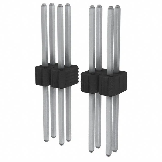
It uses a standard 0.100" (2.54mm) pitch on both the mating interface and row spacing, which matches the legacy 0.100" grid common on prototyping boards and many production PCBs. All 40 positions are loaded with square male pins made of phosphor bronze, finished with a 100.0µin (2.54µm) tin layer on the mating surface and tin on the solder posts. The through-hole termination provides a robust solder joint for boards that see mechanical strain from cable harnesses or repeated mating cycles.
With a 0.100" row spacing, the dual-row layout occupies a 0.200" wide footprint plus keep-out, which fits standard 0.100" grid prototyping boards. This current level supports logic-level power, sensor inputs, and low-current driver outputs. For applications requiring higher current per circuit, a thicker gold plating or a larger pitch connector would be needed — the tin finish here is cost-effective for moderate-duty signal interconnects.