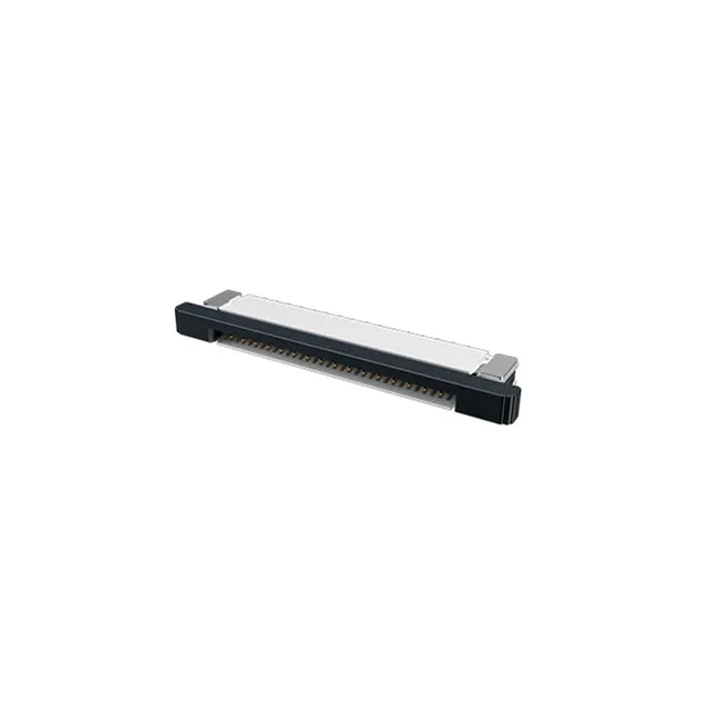
1.00 mm pitch, 26-position FFC/FPC ZIF — board-fit decisions
The F52R-1A7H1-11026: The 1.00 mm pitch sets the trace fan-out density on the PCB — at this spacing, a 26-position connector fits a 26 mm board edge footprint, leaving room for via escape on a two-layer board if the traces route between pads. Rated 0.5 A per contact at 50 V, this is a signal-only interconnect — the current ceiling is set by the narrow contact beam and the 1.97 µinch gold flash, not the housing thermal limits.
Right-angle SMT with solder retention — reflow and z-height
Gold contacts at 1.97 µinch — 30 mating cycles in practice
The gold flash on phosphor bronze contacts is 1.97 µinch (0.050 µm) — this is a thin hard-gold layer that protects the base metal from oxidation during the rated 30 mating cycles. 30 mating cycles is the manufacturer's endurance rating — in a field-service application where the connector is cycled monthly, that is roughly 2.5 years of service life at the contact interface before fretting corrosion risk increases.
Active production — sourcing posture
RoHS compliant per.
The 25-position sibling F52R-1A7H1-11025 shares every other spec: 1.00 mm pitch, 0.5 A rating, gold contacts, ZIF slide lock, same 2.00 mm height. The only difference is one fewer circuit — if the BOM can drop a signal line, the 25-position part is a drop-in footprint match.