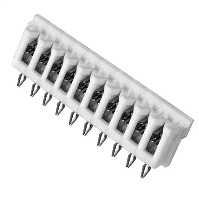
IDC Termination for Discrete Wire Harnesses
The JST 10DB-6S(LF) is a 10-position IDC connector from the DB series, designed for terminating individual stranded wires into a single-row, 0.098" (2.50mm) pitch housing. The closed-end white housing prevents contact stubbing during mating and provides polarization. It accepts 24-28 AWG stranded wire, making it suitable for internal harness wiring in control panels, test equipment, and consumer electronics where discrete wire routing is preferred over ribbon cable. The 0.098" cable pitch matches the board-side pitch, so the wire-to-board transition maintains consistent spacing across the connector. The through hole press-fit mounting allows solderless board attachment — the compliant press-fit tail holds the connector in the plated through hole without reflow, which is useful for high-reliability assemblies where rework access is needed or where wave soldering is not available.
Sizing the Wire for the IDC Slot
The wire gauge acceptance is 24-28 AWG stranded. This is the range the IDC slot is tuned for — using a wire outside this range risks either an unreliable connection (too thin) or damage to the contact beam (too thick). The stranded requirement means solid wire is not recommended; the individual strands deform to fill the slot, which solid wire cannot do reliably. The contact finish is tin-lead. For a connector that is mated and unmated only during initial assembly and occasional service, tin-lead is adequate.
Board Layout and Mating
The board-side pitch is 0.098" (2.50mm), single row. The PCB footprint requires ten plated through holes at that pitch, with the press-fit tails requiring a specific hole diameter — typically 0.040" (1.02mm) for compliant press-fit, but verify the exact drill size from the JST drawing. The closed-end housing means the mating half (a pin header, typically the JST DB series male header) enters from the open side only, preventing reverse mating.