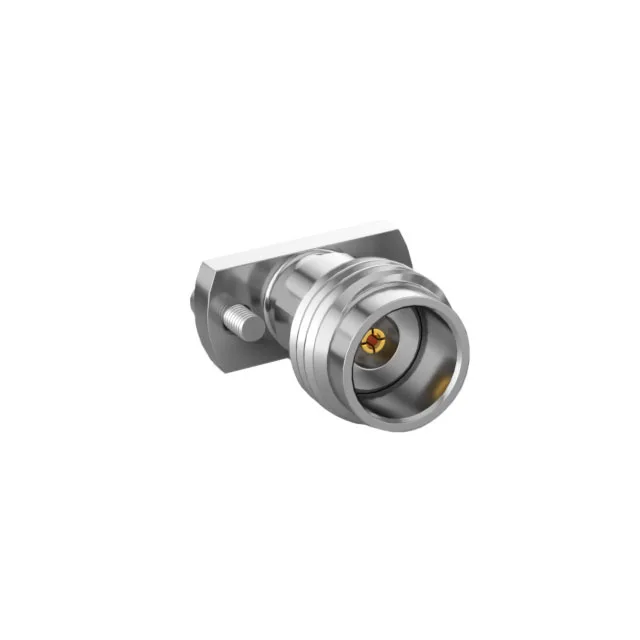
2.4mm Precision Jack for DC to 50 GHz Signal Paths
The Samtec 240-J-P-EP-ST-CM-2 is a 2.4mm (APC-2.4, OS-50) jack, female socket from the 240 Series, designed as a precision RF interconnect for applications that need a controlled 50 Ohm transmission line from DC through 50 GHz. The 2.4 mm interface is the standard for millimeter-wave test equipment, high-speed data converters, and instrumentation backplanes where signal integrity at Ka-band and above is non-negotiable.
Compression Termination Preserves the Launch
The center contact terminates by compression, not solder. That matters at 50 GHz: a soldered joint introduces a dielectric discontinuity and a thermal stress point on the polyetherimide (PEI) insulator. Compression termination clamps the center conductor directly, keeping the impedance through the launch consistent with the 50 Ohm line. The shield terminates via screw, which gives a positive mechanical ground reference to the chassis or test fixture flange.
What the 50 GHz Ceiling and 500 Cycles Mean for Your Setup
The 50 GHz maximum frequency is the upper end of the 2.4 mm connector class — this jack will pass a clean signal through the full Ka-band (26.5–40 GHz) and into the V-band window up to 50 GHz without a mode transition. Below that, the return loss and insertion loss are characteristic of a precision 2.4 mm interface. The 500 mating cycles rating is high for a millimeter-wave connector; typical SMA or 2.92 mm connectors are spec'd at 100–200 cycles. The threaded coupling and stainless steel body mean the connector can survive the torque of repeated wrench-tightening in a test rack without galling the threads or deforming the flange.
Comparing the 240-J-P-EP-ST-CM-2 to the 185-J-P-EP-ST-CMM-1
The 185-J-P-EP-ST-CMM-1 is the 1.85 mm (65 GHz) sibling in the same mechanical format: flange-mount, compression termination, stainless steel body, gold-plated beryllium copper center contact, 500 mating cycles. The 240-J-P-EP-ST-CM-2 uses the 2.4 mm interface and is rated to 50 GHz; the 185-J-P-EP-ST-CMM-1 uses the 1.85 mm interface and is rated to 65 GHz. Both are 50 Ohm, single-port jacks with threaded fastening and identical termination style. The choice between them is driven by the upper frequency your signal chain needs and the mating interface already on your cable or test port — a 2.4 mm plug will not mate with a 1.85 mm jack, and vice versa. If your system tops out at 50 GHz, the 240-J-P-EP-ST-CM-2 is the correct interface; if you need headroom to 65 GHz, the 185-J-P-EP-ST-CMM-1 is the match.