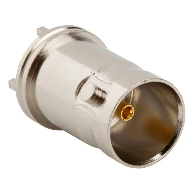
The 031-70536-12G: It carries a 12 GHz frequency ceiling — unusually high for a 75 Ohm BNC, which typically tops out around 1–4 GHz in standard video coax applications. The 75 Ohm impedance targets video distribution, CCTV, telecom baseband, and data-over-coax signal paths where the 50 Ohm standard of RF test gear would create a mismatch.
Why 75 Ohm and 12 GHz Matter for Your Signal Path
The 12 GHz max frequency means this jack handles high-resolution digital video (3G-SDI, 12G-SDI) and data rates well beyond legacy analog video.
Through-Hole Termination and Board Layout Fit
The through-hole solder termination (center pin and shield) gives a mechanically robust joint on the PCB — the shield solder tabs handle the bayonet lock's mating forces, so the signal pins don't bear the strain. The footprint is a standard BNC through-hole pattern; confirm the hole diameters and keep-out zone against your board stack-up. The tin-plated brass body is the ground return path — the shield termination is soldered, not crimped, so the PCB layout must provide a solid ground plane under the connector for best shielding effectiveness at 12 GHz.