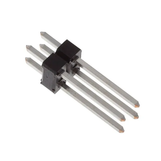
Board Layout Fit: 0.100" Pitch, 4 Positions, Dual Row
The 77313-452-04LF: The 4 positions are loaded across two rows, so the PCB footprint needs two rows of 2 holes spaced 0.100" apart, with a row-to-row spacing of 0.100" (2.54mm). The 0.120" (3.05mm) solder post length gives enough stand-off for wave-solder through a standard 1.6mm board without bottom-side bridging. Overall contact length is 0.594" (15.09mm), with a 0.374" (9.50mm) mating tail — enough to reach through a mating receptacle and still leave clearance for the housing body.
Current and Contact Finish: Tin-on-Tin for Low-Cycle Duty
Tin-on-tin contacts can frett in high-vibration or repeated-mate environments; for those, the gold-plated siblings (77313-101-04LF or 77313-818-04LF) are a better fit. The post finish is also tin (78.7µin), which solders reliably with standard lead-free wave profiles.
The base product number 77313 covers a family of BergStik headers with varying pin counts and plating options. The -04LF suffix indicates 4 positions with tin finish. No official direct replacement exists from the same manufacturer; the closest functional alternative with gold plating is 77313-101-04LF (30µin gold mating) or 77313-818-04LF (15µin gold mating), both active and same footprint.
Mating Half and Build-to-Print Checklist
For a build-to-print BOM, you need the header body (this part), the mating receptacle (sold separately), and the crimp terminals or IDC cable assembly if using a wire-to-board receptacle.