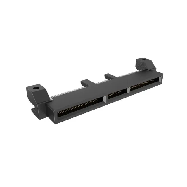
Edge Connector for High-Density Card Interfaces
It uses a 0.024" (0.60mm) pitch across two rows, with cantilever contacts in a dual readout configuration — meaning each contact pair reads both sides of the PCB card. The straddle mount (board edge, straddle mount) places the connector astride the PCB edge, so the card slot aligns with the board's edge rather than sitting on the surface. This is the typical layout for a mezzanine or riser card interface in a server, switch, or storage backplane where the card plugs in parallel to the main board.
What the 0.60mm Pitch Means for Your Board Layout
At this pitch, the card edge fingers need to be 0.30mm wide with 0.30mm spacing to match the contact layout. The 140 positions are organized across two rows, with the positions per bay/row split as 28, 14, and 28 — likely corresponding to three separate card edge segments or keying zones. The card thickness is specified as 0.062" (1.57mm), which is standard for a 1.6mm PCB, so the connector's card slot is gapped for that thickness. If your card is thicker or thinner, the contact normal force changes and the connector may not seat properly.
Gold Plating and Contact Reliability
The unthreaded straddle mount opening (0.087" / 2.20mm) accepts a locating pin or alignment feature on the card edge to prevent mis-insertion.
Comparing to the 168-Position Sibling
The closest functional alternative in the same Mini Cool Edge 0.60mm series is the ME1016813401201, which shares the exact same pitch (0.60mm), contact finish (30.0µin gold), card thickness (0.062"), straddle mount, and dual readout. The 168-position variant adds 28 more contacts, which changes the card edge finger layout and the PCB routing density. If your BOM calls for 140 circuits, this is the correct part; if you need more I/O on the same card edge, the 168-position version is a drop-in swap on the connector footprint — same mounting hole pattern and card slot width.