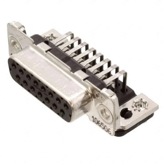
It's a right-angle, through-hole solder version with threaded 4-40 inserts on the flange for panel-mount or mating with the corresponding plug's hardware. The 0.406-inch backset spacing (10.30 mm) positions the board edge relative to the panel face — a dimension that matters when the connector sits inside a cutout with limited rear clearance. That plating thickness tells you this connector was designed for repeated mating cycles — field-service reconnects, test-equipment harness swaps, or any assembly where the connector sees more than a few mate-unmate events over its life. This isn't a sealed connector — no IP rating — so it belongs in a dry, indoor or protected location where the shell's tin plating and the housing's V-0 rating are sufficient.
The panel-mount flange with 4-40 threaded inserts gives a second anchor point if the application calls for it, but the board lock alone is enough for many installations. The 0.406-inch (10.30 mm) backset spacing defines the distance from the mounting flange face to the rear of the connector body. When you're designing the board-to-panel clearance, that dimension sets the minimum space needed behind the panel for the connector body and the solder tails. Standard footprint — the PCB layout pattern is well-documented in the AMPLIMITE HD-20 datasheet.