Board Fit and Footprint Decisions
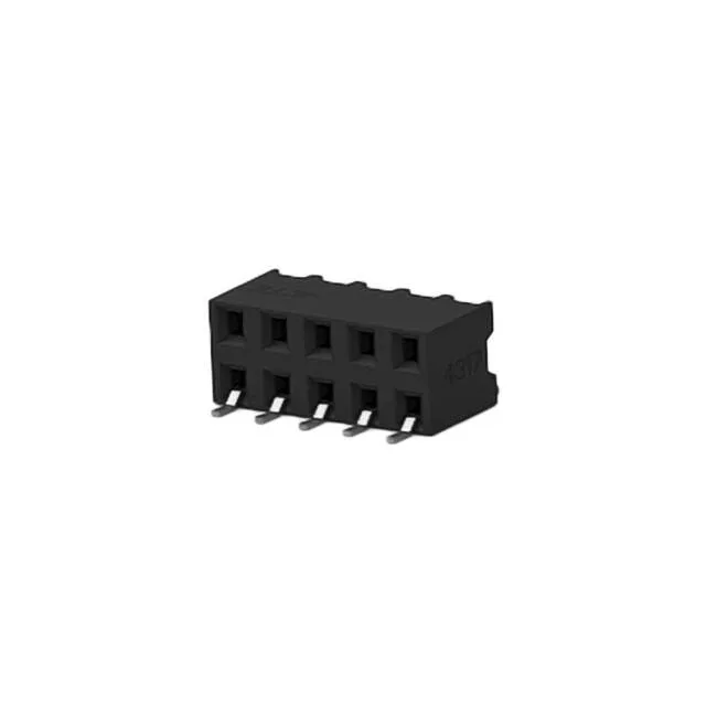
The 2.00mm pitch on both rows sets the board footprint — each contact pair sits on 2.00mm centers, row to row also at 2.00mm. That gives you a compact 4.00mm-wide keep-out on the PCB for a 10-signal interconnect. Rated 2A per contact at 125V, with a gold mating finish (3.94µin) over phosphor bronze contacts. The gold layer is thin — typical for signal-level duty where the connector sees occasional mate/unmate cycles, not continuous field reconnection. The tin-plated solder tails (12.0µin) reflow reliably with standard SAC305 paste profiles.
How It Compares to Similar AMPMODU Receptacles
Against the 1376775-2 (5-position, 3A, 250VAC, gold 8.00µin): the 1-2307729-0 doubles the position count but drops to 2A per contact. The thicker gold on the 1376775-2 (8.00µin vs 3.94µin) supports more mating cycles — if your application cycles the connector quarterly, the 1376775-2 is the better endurance pick; for a one-time board-to-board link, the 1-2307729-0's thinner gold is adequate and saves cost.
Mating and Orientation Constraints
Right-angle orientation means the mated board sits perpendicular to the receptacle board — typical for mezzanine or card-edge stacking where the z-height is tight. Insulation height is 0.161" (4.10mm) above the board surface, which sets the minimum clearance to adjacent components. Mates with a matching 2.00mm-pitch AMPMODU header (not included). The square contact shape (0.64mm typical) engages with the header's square pin. Confirm header pin length and board stack-up before committing the BOM — the right-angle receptacle's mating interface height is fixed by the 4.10mm insulation height.