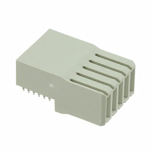
It accepts female blade sockets in a single row, with all 5 positions loaded for pure power delivery — no signal contacts. The right-angle orientation and board-edge mounting put the power path perpendicular to the PCB, which is the typical layout for a plug-in card feeding a backplane bus bar.
Press-Fit Termination — No Solder, No Rework
The press-fit termination is the defining feature here. Instead of solder, the compliant pin compresses into the plated through-hole, creating a gas-tight joint. That means no solder voids, no wicking, and no rework — the connector is pressed into the board in one operation. For a backplane assembly with dozens of connectors, press-fit eliminates the thermal stress of wave soldering and makes field replacement of a damaged connector feasible: desolder a 5-position power header from a multi-layer backplane and you risk lifting the barrel. Press-fit pins pull out cleanly with the right tool. Board layout needs clearance behind the connector for the press tool anvil — typically 3-5 mm of keep-out on the opposite side.
The blade power contact style is a standard TE UPM format — the female socket blades accept the male tabs from the header. The single-row, 5-position layout is keyed by the housing geometry; there is no secondary keying option in this series. Confirm the header part number from the same UPM family to ensure the blade width and pitch align.