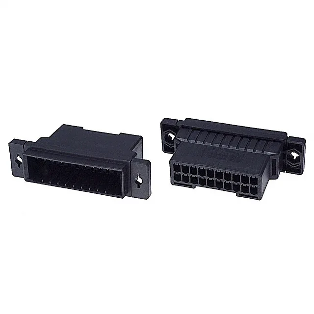
Housing for a 20-Circuit Power Harness
The 3.81 mm pitch and 5.08 mm row spacing give enough room for 16-20 AWG power wiring without crowding the cavity wall. The mounting flange on each end secures the housing to a panel — useful when the connector sees cable strain or the harness is pre-assembled before final installation.
What the 3.81 mm Pitch and 20 Positions Mean for Your Fit
The 0.150" (3.81 mm) pitch sets the board footprint for the mating header — a common spacing for medium-current power connectors, wider than signal-pitch headers so the PCB traces can carry 5-8 A per circuit without necking down. 20 positions in two rows means the header footprint is about 38 mm long by 9 mm wide (plus the mounting flanges), which fits a standard industrial PSU or motor-drive board.
Wiring Note — Order the Terminals Separately
This housing ships without contacts. The housing accepts the terminal after crimping; the push-pull fastening holds the terminal in the cavity without a secondary lock. For a production harness, order the housing and terminals together so the assembly line has both halves ready. The mounting flange is the only retention feature on the housing itself — the cable strain is managed by the terminal crimp and any external cable tie, not by the housing latch.