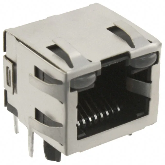
8P8C Shielded RJ45 Jack with Integrated Status LEDs
It is the part to specify when a standard Ethernet port needs EMI containment and on-connector link/activity indication — the dual yellow and green LEDs save the board designer from placing separate indicator LEDs elsewhere. Through-hole mounting gives the shell the mechanical anchor it needs against the lever-out force of a stiff Ethernet cable.
Shielding and EMI Finger — What It Buys You
Board Layout: Right-Angle, Through-Hole, Board Guide
The through-hole termination provides the mechanical strength to withstand repeated plug insertions; an SMT jack on the same footprint would risk pad lift under the same duty. The board guide feature is a pair of plastic alignment posts that locate the jack during wave soldering, preventing the connector from skewing off the pad pattern. The tab direction is up, meaning the latching tab on the RJ45 plug faces upward when the jack is mounted on the top side of the board.