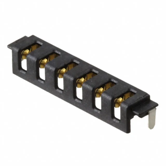
It sits on a 0.118" (3.00 mm) pitch in a single row — that pitch is the dimension you'll lay out on the PCB pad pattern, and it matches the mating blade header's pin spacing. It's sized for the repeated mate/unmate cycles a battery interconnect sees in assembly, test, or field service. The housing is black liquid crystal polymer (LCP), which holds up to the reflow temperatures of lead-free solder profiles.
Board Fit and Footprint Notes
Single-row, 6 positions — the footprint is narrow along the board edge, which suits the space constraints of a battery management system PCB or a handheld device main board. The solder retention feature adds surface-mount anchor pads outside the signal row; those pads take the mechanical load during cable insertion, so the signal joints aren't the only thing holding the connector down. Mating half is the corresponding FBIS-II blade header — the blade width and pitch are fixed by the series design.