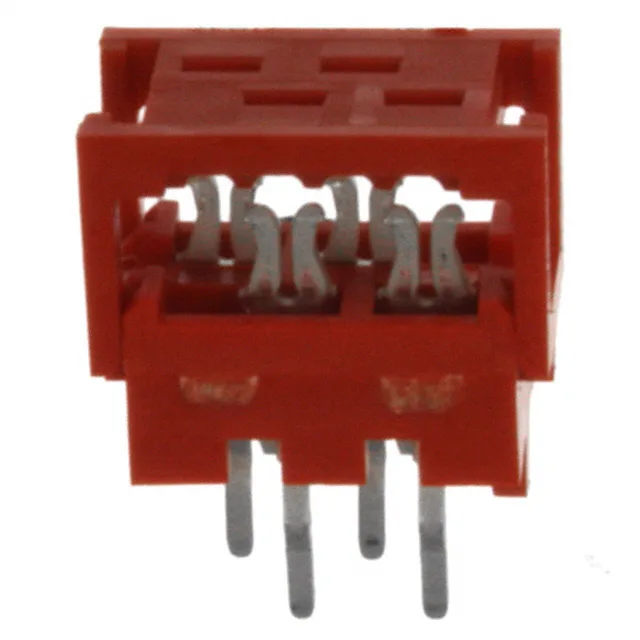
4-Position Micro-MaTch DIP Header for 28 AWG Ribbon — IDC Termination, Press-Fit Mount
The 215570-4: It accepts 28 AWG stranded or solid wire on a 0.050" (1.27mm) cable pitch — that's the pitch that has to match your ribbon, not the board-side 0.100" (2.54mm) pitch. Watch pin-one every press: the red housing gives a visual cue, but the keying is in the IDC slot alignment. The press-fit through-hole mounting means no solder wicking up the contacts — the compliant pin cold-forms into the plated through-hole, which makes rework possible if you mis-press a conductor.
Pitch and Wire Gauge — What Fits
The cable-side pitch is 0.050" (1.27mm) and the board-side pitch is 0.100" (2.54mm). This is a common split-pitch IDC header: the ribbon conductors land at 1.27mm spacing, then the two rows spread to 2.54mm at the board interface. The 28 AWG wire gauge is the only supported size — the IDC slot geometry is cut for that conductor diameter. Trying 26 AWG or 30 AWG will either miss the slot or damage the insulation. The 4 positions are all loaded, so you get a full 2x2 matrix.
Press-Fit Termination — No Solder, No Wave
The through-hole press-fit termination eliminates the soldering step. The compliant pin design deforms elastically as it enters the plated hole, creating a gas-tight joint. This is standard for backplane and high-reliability assemblies where thermal shock from wave soldering is a concern. The trade-off: the PCB hole diameter and plating thickness must match the press-fit pin geometry — check the application note for the recommended finished hole size before committing the board layout.