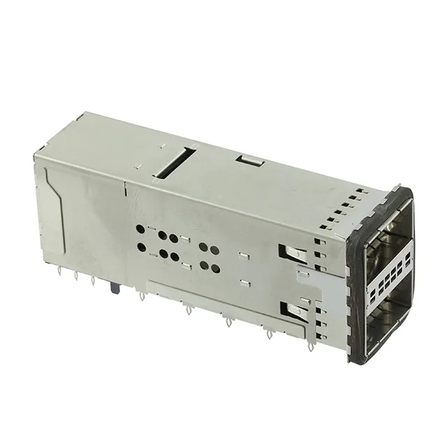
It carries 76 positions arranged as 38 per port, laid out for the standard QSFP+ / QSFP28 electrical interface. The press-fit termination and right-angle orientation place the cage parallel to the board edge, designed for high-density I/O panels on switch, router, or server backplanes where solderless assembly and reworkability are requirements.
Press-Fit and Right-Angle Mounting
Press-fit termination means the compliant pins are pressed into plated through-holes — no solder joint, no reflow profile to manage. That suits backplane assemblies where the connector goes through the board and the cage sits on the opposite side, or any line where eliminating a wave-solder step saves process cost. That geometry is standard for faceplate I/O on line cards and mezzanine modules.
EMI Shielding Built Into the Cage
The cage is listed as EMI shielded — the stamped metal enclosure around each port provides a ground path for common-mode noise radiated from the high-speed differential pairs. For 25 Gbps per lane (QSFP28) or 10 Gbps per lane (QSFP+), that shielding is what keeps the port emissions within FCC / EN 55032 Class A limits. The ganged 2x1 design shares a common shield wall between the two ports, saving board space over two separate single-port cages.
Contact Plating and Signal Integrity
That thickness supports the mating cycle life expected in a QSFP-style interface — typically 100 to 250 cycles before the gold wears through to the nickel underplate. For a port that gets re-cabled during field upgrades or test-lab reconfiguration, 30.0µin gold is the standard grade that avoids contact resistance drift over the service life. The press-fit tail is tin-plated for the interference fit into the PCB hole.