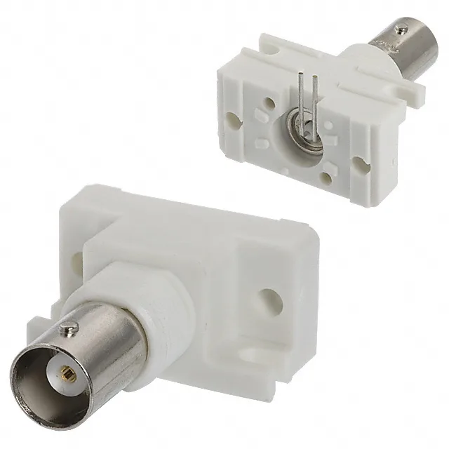
It mounts through a panel flange and terminates to the board via a right-angle solder tail — a common layout for enclosure-edge RF ports where the PCB runs parallel to the panel face.
RF and mechanical ratings
The 50 Ohm impedance sets the characteristic line match for the cable and PCB trace. The 4 GHz ceiling means the connector stays within its return loss spec up to that frequency.
This is a panel-mount jack with a flange that bolts to the enclosure wall, and the center contact and shield terminate through a right-angle solder tail to the PCB.