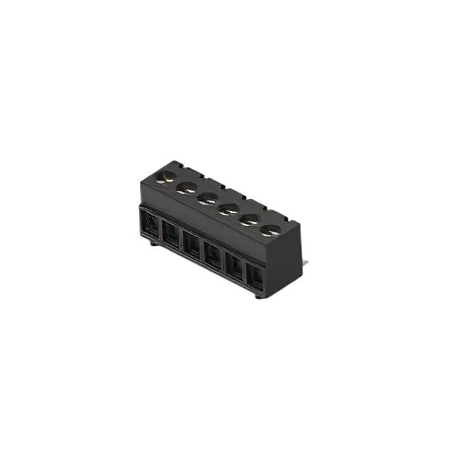
Pitch, Positions, and Board Footprint
The 2383945-6: The 0.150" (3.81mm) pitch and 6 positions per level give a total width of about 0.90" (22.86 mm) across the terminal strip. The SMD footprint means the block is reflow-soldered alongside other surface-mount components, which saves a wave-solder pass but demands the board pads match the 3.81 mm spacing exactly.
The 12 A rating assumes all circuits are loaded simultaneously at 25°C ambient; derate above that per the polyamide housing's thermal limits. The 300 V rating is sufficient for most single-phase control voltages within an enclosure.
Wire termination uses a rising cage clamp driven by an M2 screw. The recommended torque is 0.5-0.6 Nm (4.4-5.3 Lb-In). The clamp accepts 16-28 AWG — solid or stranded — and the nickel-plated copper alloy clamp and screw resist corrosion in humid environments. No ferrule is required, though ferruled stranded wire seats cleanly under the clamp.
Surface-mount termination with a horizontal mating orientation — the wire entry is parallel to the PCB, so the block sits flat on the board and the wires exit along the board edge. No through-hole pins or panel-mount hardware; the SMD pads and the solder joint bear the mechanical load.