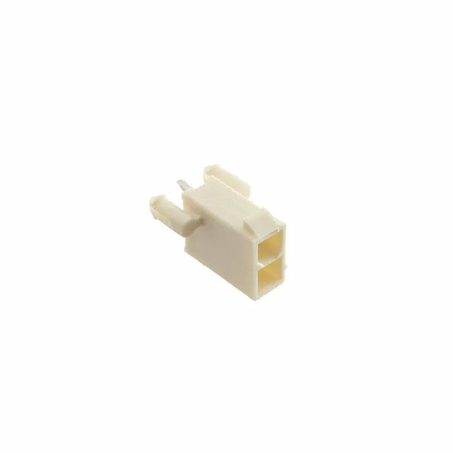
TE Connectivity AMP Connectors 2825274-2 — Pin Headers

2825274-2 TE Connectivity VAL-U-LOK Header, 2-Pos, 13 A

MPN2825274-2
Active

TE Connectivity VAL-U-LOK, Header, 2 Positions, 2 Row, 0.165" (4.20 mm) Row Spacing, Through Hole, Solder, Tin Mating/Post, 13 A, 600 V, Board Lock, Glow Wire Compliant, UL94 V-0

$0.8300Ref. price · indicative, final on quote
RoHSROHS3 Compliant
SeriesVAL-U-LOK
Sourced new & surplus through independent channelsAuthenticity-screened · ESD-safe packingListing updated Aug 2026

Specifications

2825274-2 key specifications
ParameterValue
SeriesVAL-U-LOK
TypeMale Pin
MountingThrough Hole
Connector typeHeader
Fastening typeLocking Ramp
Voltage rating600V
Current rating13A
Operating temperature-40°C~105°C
Contact materialCopper Alloy
Insulation colorNatural
Insulation height0.504\" (12.80mm)
Insulation materialPolyamide (PA), Nylon

All specifications

2825274-2 additional specifications
ParameterValue
Material flammability ratingUL94 V-0
StyleBoard to Cable/Wire
PackageTray
FeaturesBoard Lock, Glow Wire Compliant
ShroudingShrouded - 4 Wall
TerminationSolder
ApplicationsAutomotive, General Purpose, Industrial, Lighting, Medical
Contact shapeSquare
Rows2
Positions2
Row spacing - mating0.165\" (4.20mm)
Contact finish - postTin
Contact length - post0.138\" (3.50mm)
Contact finish - matingTin

Product details

What This 2-Position Header Does in a Harness

The 2825274-2: The 13 A per contact rating at 600 V means this header can handle a single power pair or a signal pair in a 24-18 AWG range without exceeding the contact temperature rise.

Current, Temperature, and Material Limits

For applications that see frequent disconnect (field-service access panels), a gold-plated sibling in the VAL-U-LOK family would extend cycle life. The UL94 V-0 flammability rating and glow wire compliance are mandatory for automotive interior and household appliance enclosures where the connector sits inside a plastic housing that must self-extinguish within 10 seconds. The 600 V rating is the dielectric withstand between adjacent circuits — in a 2-position part, that's the voltage stress across the two pins, not a line-to-ground rating.

Mating Half and PCB Footprint

The 0.165" (4.20 mm) row spacing and 0.138" (3.50 mm) post length set the PCB footprint: the through-hole pattern is a 2×1 grid with 4.20 mm between rows. The board lock adds two additional through-hole anchors outside the signal pin pattern — confirm the PCB layout accommodates these extra holes before committing the BOM.

Frequently asked questions

What is the mating connector for 2825274-2?

This header mates with VAL-U-LOK receptacle housings that accept the matching crimp terminals. The 2-position, 2-row receptacle housing (e.g., TE 1-794617-2) is the direct mating half. Confirm the circuit count and row spacing match your harness design.