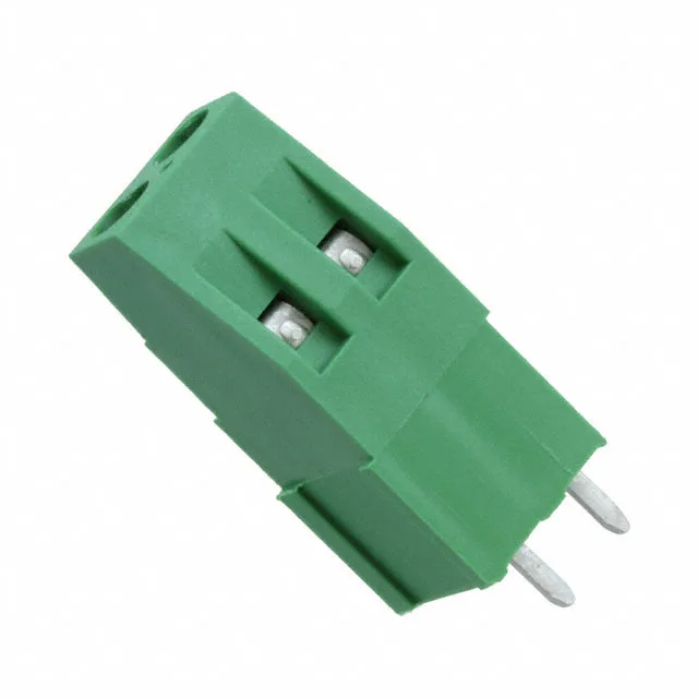
It uses a screw-driven rising cage clamp — turning the M3 screw lifts a nickel-plated brass clamp plate that presses the conductor against the current bar, creating a gas-tight connection suitable for both solid and stranded wire from 12 AWG up to 30 AWG. The green polyamide (PA66) housing carries a single level of termination, and the side interlocking feature lets you gang multiple blocks side-by-side without a separate jumper bar — useful when building a multi-position distribution point on the same PCB.
17.5 A at 300 V — Power Handling and Wire Range
Rated 17.5 A at 300 V, the 282901-2 covers typical control-circuit and low-power distribution duties — think PLC I/O modules, industrial sensor hubs, or HVAC controller boards. The 12 AWG maximum wire size means it can land a fairly heavy power feed; the 30 AWG minimum handles fine signal wiring. The rising cage clamp applies a controlled clamping force (torque spec 0.79 Nm / 7.0 Lb-In) that avoids conductor damage while maintaining low contact resistance over temperature cycles.
Side Interlocking and Board Layout
The side interlocking feature (listed as 'Interlocking (Side), Mid Wire Entry Level') allows mechanical keying between adjacent blocks — you snap them together on the PCB to form a multi-position strip without needing a separate jumper bar for mechanical alignment. For a 4-position or 6-position distribution point, ordering two or three of these 2-position blocks and interlocking them side-by-side is a common workaround when the exact position count isn't stocked as a single part. The through-hole mounting with 5.08 mm pitch gives a straightforward footprint: two 1.0 mm diameter holes per position on a 5.08 mm grid, with the screw heads accessible from the top after soldering.