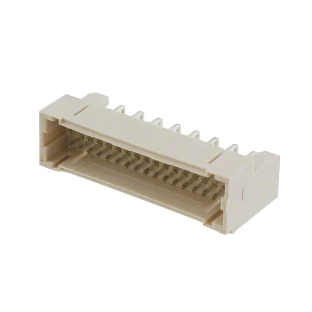
The 3-292262-2: The 1.50 mm pitch sets the board footprint and the per-contact current ceiling. At this pitch, the trace routing between pads is tight — a 4-layer board is the safe bet for fan-out on all 32 positions. The 32 positions are all loaded — no empty slots to waste board real estate.
Through-hole right-angle — board-edge routing
Right-angle orientation places the wire exit parallel to the PCB, useful for board-edge connectors where the cable bundle runs along the enclosure wall. The 0.118" (3.00 mm) solder tail length is standard for a 1.6 mm board — the tail protrudes enough for a reliable wave-solder fillet without bottoming out on the board.
Shrouded 4-wall with detent lock — vibration duty
The shrouded 4-wall design protects the male pins from bending during mating and prevents off-angle insertion that could short adjacent contacts.
Tin contacts — signal duty, not high-cycle
Tin-on-tin mating finish is rated for moderate mating cycles — typically 25-50 cycles before fretting corrosion becomes a concern. In a field-service application where the connector is cycled more than a few times a year, gold-plated contacts are a better choice.