The 3-794638-4: This 4-position, 2-row header uses a 3.00mm pitch on both rows, setting the board footprint for the mating wire receptacle. The shrouded 4-wall housing guides the plug during blind mating and prevents contact damage from off-angle insertion. In a vibration-prone environment—like an industrial cabinet or automotive interior—this latch keeps the pair mated without relying on friction alone.
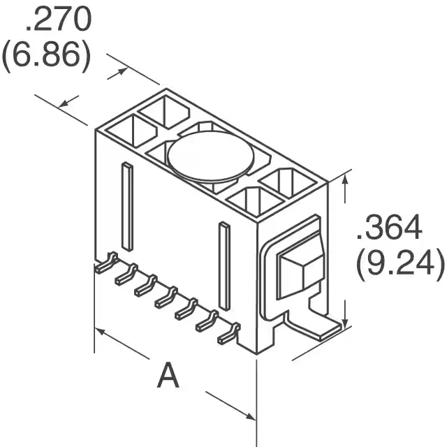
3-794638-4 TE Connectivity Micro MATE-N-LOK Header SMD 4
MPN3-794638-4
Active
TE Connectivity AMP Connectors Micro MATE-N-LOK header, SMD, 4 circuits, 2 rows, 3.00mm pitch, gold mating finish, shrouded with locking ramp, solder retention, UL94 V-0, -40°C~105°C.
$3.3100Ref. price · indicative, final on quote
RoHSRoHS Compliant
SeriesMicro MATE-N-LOK
Sourced new & surplus through independent channelsAuthenticity-screened · ESD-safe packingListing updated Aug 2026
Specifications
| Parameter | Value |
|---|---|
| Series | Micro MATE-N-LOK |
| Type | Male Pin |
| Mounting | Surface Mount |
| Connector type | Header |
| Fastening type | Locking Ramp |
| Voltage rating | 250V |
| Current rating | Varies by Wire Gauge |
| Operating temperature | -40°C~105°C |
| Contact material | Brass |
| Insulation color | Black |
| Insulation height | 0.364\" (9.25mm) |
| Insulation material | Polyamide (PA), Nylon |
All specifications
| Parameter | Value |
|---|---|
| Material flammability rating | UL94 V-0 |
| Style | Board to Cable/Wire |
| Package | Tape & Reel (TR); Cut Tape (CT) |
| Features | Solder Retention |
| Shrouding | Shrouded - 4 Wall |
| Termination | Solder |
| Applications | General Purpose |
| Contact shape | Square |
| Rows | 2 |
| Pitch | 0.118\" (3.00mm) |
| Positions | 4 |
| Row spacing - mating | 0.118\" (3.00mm) |
| Contact finish - post | Tin |
| Contact finish - mating | Gold |
| Contact finish thickness - post | 100.0µin (2.54µm) |
| Contact finish thickness - mating | 30.0µin (0.76µm) |
Product details
Frequently asked questions
What is the mating connector for 3-794638-4?
This header mates with a Micro MATE-N-LOK receptacle housing (e.g., 3-794637-x series) that accepts crimp terminals.
What is the recommended PCB layout for 3-794638-4?
The footprint uses a 3.00mm pitch between positions and 3.00mm row spacing. The SMD pads should match the solder tail dimensions; the shrouded housing requires a keep-out zone around the 9.25mm insulation height for clearance above the board. Refer to the product drawing for exact pad geometry and stencil aperture.