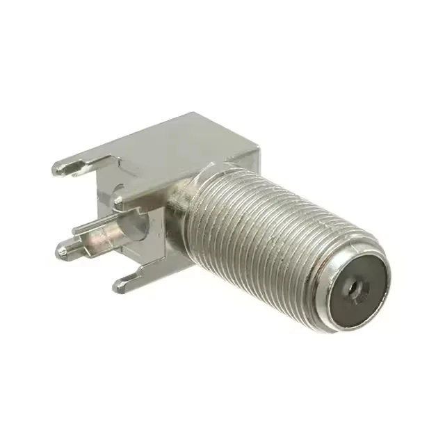
The 5-1634540-0: It mounts through a bulkhead panel using a front-side nut, with the contact terminated via solder to a through-hole PCB pad, and the shield soldered to ground. The zinc alloy body with nickel finish and threaded fastening gives a secure, shielded mate typical of F-type connectors used in CATV, satellite, and broadband distribution equipment.
If you are maintaining an existing design, verify the mating interface and impedance match before substituting a different F-type jack.
RF Specs and Mounting Detail
The 75 Ohm impedance and 1 GHz frequency ceiling define the usable signal bandwidth — this jack is sized for standard-definition video, broadband data, and L-band satellite IF feeds, not for high-frequency digital or microwave links. The right-angle through-hole termination requires the PCB footprint to account for the centre pin offset and the solder shield tabs — the board layout engineer should pull the TE application drawing before committing the land pattern.