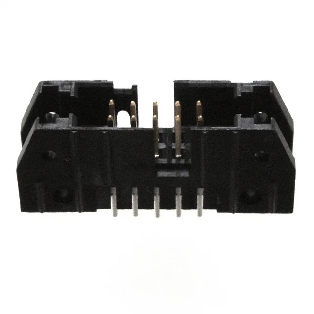
The 5102155-1: It is a shrouded – 4 wall design, meaning the plastic walls surround the pins on all four sides. That shroud protects the pins from bending during mating and guides the cable-side plug into alignment — a detail that matters when the header is on a board that gets serviced in the field.
Board footprint and pinout dimensions
The header stands 0.684" (17.37mm) overall from the board surface to the tip of the mating pin. The mating pin length is 0.240" (6.10mm), and the solder tail below the board is 0.155" (3.94mm) — enough to clear a standard 1.6mm PCB and still have a visible fillet on the solder side. Row spacing is 0.100" (2.54mm), matching the pitch, so the 10 positions occupy a 5 x 2 grid that fits a standard 0.100" footprint. A keying slot and mounting flange are built into the housing. The keying slot prevents inserting the wrong cable-side plug; the mounting flanges let you screw the header to the board for extra mechanical retention against cable strain.