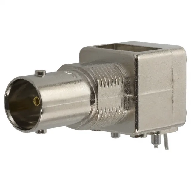
It mates with standard BNC plugs using a bayonet lock for quarter-turn engagement. The centre contact is beryllium copper with gold plating — a combination that holds up across the rated 500 mating cycles without signal degradation from corrosion or fretting. The 500 V voltage rating gives headroom for composite video, baseband data, and low-power RF signals without derating concerns.
75 Ohm vs 50 Ohm — why it matters
The impedance mismatch between a 75 Ohm jack and a 50 Ohm cable or connector creates a reflection at the junction that degrades signal quality above a few MHz. The 2 GHz maximum frequency of the 5222092-1 suits composite video, SDI, and baseband data links. The 1057230-1 reaches 22 GHz, but that bandwidth is unnecessary for 75 Ohm video paths and the 50 Ohm impedance would introduce a mismatch.
Mates with any standard BNC plug (male) using the bayonet lock — no special keying or orientation required. The shield is terminated by soldering to the bulkhead or PCB ground plane; the centre contact is solder-terminated to the signal trace. The front-side nut secures the jack to the panel before soldering, which keeps the connector square to the panel face during assembly. The right-angle PCB tail routes the signal trace parallel to the board surface, useful when the board sits directly behind the bulkhead. Confirm the trace width and dielectric stack-up to maintain 75 Ohm characteristic impedance through the launch — the connector itself is impedance-controlled to 75 Ohms, but the transition to the PCB trace is where mismatches appear.