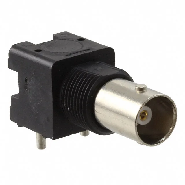
It carries a 2 GHz max frequency ceiling and a 500 V rating, putting it in the class of BNC connectors used for composite video, SDI, and RF test equipment up to the lower UHF band. This is the 75 Ohm variant of the standard BNC interface — the centre contact and dielectric geometry are sized for 75 Ohm, not the 50 Ohm that dominates RF bench work. If your system runs 50 Ohm, this jack will present an impedance mismatch and a return loss penalty; the 5415633-1 is for the 75 Ohm side of the connector world. The mounting arrangement combines a panel-mount bulkhead with a front side nut and right-angle through-hole solder tails. That means the connector clamps to the panel face while the signal and ground legs drop onto the PCB at a right angle — useful when the board sits parallel to the panel inside an enclosure and you need the cable entry on the panel face. The bayonet lock gives a quarter-turn mate that holds without tools — standard BNC field behaviour. The board guide and isolated features help align the connector during PCB insertion and keep the shell from shorting to nearby traces.
Mounting and Termination Detail
Shield termination is solder — the braid or foil drain wire from the coax solders to the shell or ground leg. Centre contact termination is also solder, so this is a solder-bucket or solder-post connection, not a crimp. That makes it a bench or low-volume assembly proposition; for high-volume coax termination you would look at a crimp-style BNC. The bulkhead front side nut means the jack installs from the outside of the panel — the nut threads onto the body from the front, so the connector body sits flush against the panel face. The right-angle tails then extend behind the panel to the PCB. This is a common arrangement for enclosure rear panels where the cable mates on the outside and the PCB sits inside.