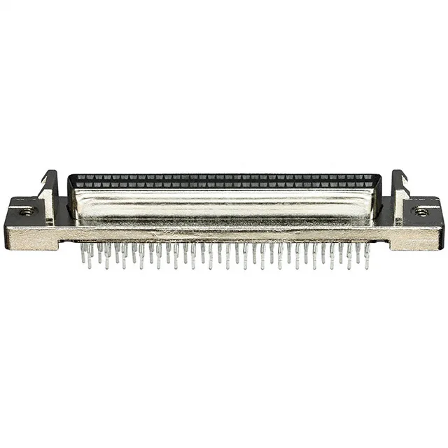
5786155-7 — TE Connectivity AMP Connectors product photo

TE 5786155-7 AMPLIMITE .050 III D-Sub Receptacle, 68 Pos

MPN5786155-7
Active

TE Connectivity AMPLIMITE.050 III D-sub receptacle, 68 positions, 2 rows, 0.050 pitch x 0.100 row spacing, press-fit termination, gold-plated phosphor bronze contacts, shielded steel shell, UL94 V-0, black PPA housing.

$22.0600Ref. price · indicative, final on quote
StockContact for availability
Lead timeIn Stock wk
MOQ1 pcs
  • New & original stockTraceable channels only — no mixed lots, no re-taped reels.
  • Factory packaging where availableSealed reels, trays and bags; cut quantities always stated on the quote.
  • Photo-verified countsEvery line counted and photographed before the box closes.
  • PayPal buyer protectionPay by T/T, PayPal or Payoneer — card payments covered end to end.

Specifications

5786155-7 Technical Specifications
ParameterValue
SeriesAMPLIMITE .050 III
GenderSignal
Mounting typeThrough Hole
Connector typeReceptacle, Female Sockets
Voltage rating30V
Current rating1A
Shell size, connector layout0.050 Pitch x 0.100 Row to Row
Operating temperature-55°C ~ 105°C
ColorBlack
Contact materialPhosphor Bronze
Dielectric materialPolyphthalamide (PPA)
Shell material, finishSteel, Nickel Plated
Material flammability ratingUL94 V-0
PackageTube
FeaturesShielded
TerminationPress-Fit
Contact finishGold
Flange featureHousing/Shell (2-56); Latchblocks
Rows2
Positions68

Product details

68-Position Shielded D-Sub for High-Density Backplane Signal Interconnects

The TE Connectivity 5786155-7 is a 68-position D-sub receptacle from the AMPLIMITE.050 III series, designed for vertical press-fit mounting through a PCB. It carries gold-plated phosphor bronze signal contacts rated 1 A each, with the 0.050 inch pitch and 0.100 inch row-to-row spacing defining the board footprint for high-density signal routing. The steel shell is nickel-plated and the housing is shielded, giving the interconnect EMI containment suitable for telecom and industrial backplane environments where signal integrity matters.

Press-Fit Termination and Board Assembly Fit

The press-fit termination eliminates soldering, which is a key advantage for backplane assemblies where rework access is limited and solder-joint inspection is impractical. The compliant press-fit pin deforms elastically into the plated through-hole, creating a gas-tight connection that survives thermal cycling. The flange features include housing/shell threaded inserts (2-56) and latchblocks for secure mating with the corresponding plug — the latchblocks provide a secondary lock against vibration-induced disconnection in rack-mounted equipment. The through-hole mounting orientation places the receptacle vertically on the board, with the shell and latchblocks providing the mechanical retention that the press-fit pins alone should not be asked to carry.

Positioning Within the AMPLIMITE .050 III Series

At 68 positions, this receptacle sits at the high-density end of the AMPLIMITE.050 III series, which also offers lower position counts such as the 50-position variant (5786155-1). The 0.050 inch pitch is common across the series, so the footprint geometry scales with position count — a 68-position layout simply extends the row length compared to a 50-position board pattern. The press-fit termination and shielded shell are shared across the series; the decision between position counts is driven by the number of signal lines the backplane needs to route.

Frequently asked questions

What is the pin pitch of the AMPLIMITE.050 III 5786155-7?

The 5786155-7 uses a 0.050 inch pitch between contacts with a 0.100 inch row-to-row spacing, as specified in the connector layout. This is the standard pitch for the AMPLIMITE.050 III series.

Does the 5786155-7 have a direct equivalent from another brand?

No pin-compatible direct replacement from Amphenol, Molex, or other brands is recorded. The AMPLIMITE.050 III series uses a proprietary 0.050 inch pitch footprint and shell geometry that does not match standard D-sub outlines. Board layout changes would be required to use an alternative connector family.