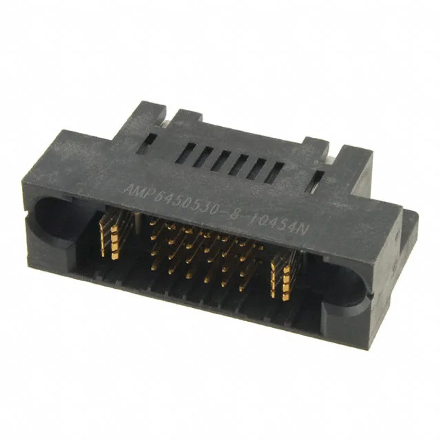
The 6450530-8 is officially listed as Obsolete. There is no direct replacement order code on record from TE Connectivity. If you are qualifying a new design, look at the current MULTI-BEAM XL catalog for an active power-blade header that matches your circuit count and pitch requirements.
Press-fit and right-angle — what it means on the board
This is the standard layout for a backplane power distribution blade: the press-fit pins survive the insertion forces of a large backplane, and the right-angle body keeps the cable or busbar run flat against the board.
The 24+2 pinout — why the circuit split matters
The 26 total positions break down as 24 signal contacts and 2 power blades. This is not a uniform array — the two power blades are physically larger and carry higher current than the signal pins. When you are matching a BOM line, confirm that your harness or backplane trace splits the circuits the same way: the signal contacts handle logic-level current, the power blades carry the main DC rail. A standard 26-position header with all identical contacts will not drop into this footprint.
Mating guide and what it mates with
This header includes a mating guide feature — alignment ribs or keying that steer the receptacle into correct orientation before the contacts engage. It mates with the matching MULTI-BEAM XL receptacle housing (not included). The press-fit tails are sized for the standard backplane PCB hole pattern; the right-angle body means the receptacle approaches from the board edge, not from above.