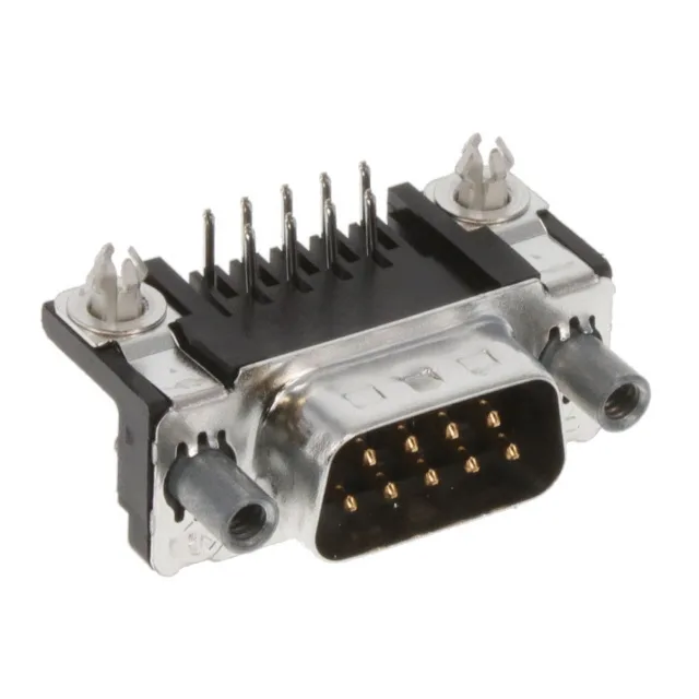
Right-Angle D-Sub Plug with Board Lock — 9 Positions
This is the male pin half of a standard DE-9 (E shell size) interface, mating with the corresponding HD-20 receptacle. Rated 6A per contact at 125V, with gold-plated brass signal contacts. The 6A figure is typical for signal-grade D-Sub contacts — sufficient for serial data lines, control signals, or low-power auxiliary circuits. These make it a better fit for EMI-sensitive designs where a standard D-Sub without grounding would let noise couple into the I/O lines. The shell is steel with tin plating, rated UL94 V-0 for the housing material.
Board Lock and Grounding — What They Do for Your Assembly
During wave or hand soldering, it holds the connector square to the board — no fixture needed. After soldering, the lock resists the lever force from a heavy cable bundle pulling on the D-Sub backshell. Without it, the solder joints alone would absorb that strain and eventually crack. The ground strap and grounding indents work together as a shield-termination system. The strap connects the connector shell to a ground pad on the PCB; the indents on the mating face contact the receptacle shell before the signal pins engage. This means any ESD or EMI current on the cable shield is diverted to ground through the shell, not through the signal contacts. For a D-Sub carrying RS-232, RS-422, or other single-ended signals in a noisy electrical environment, this is the difference between a clean link and intermittent data errors.