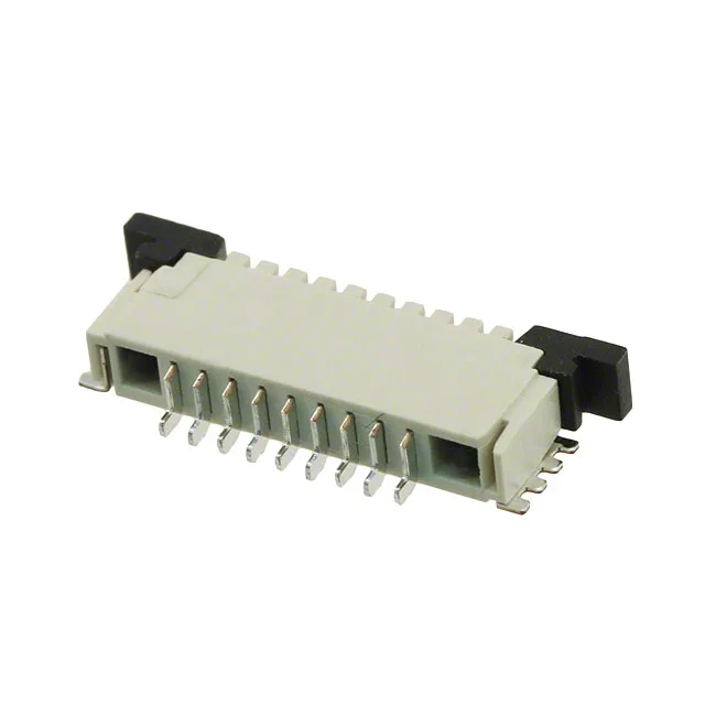
Why this FPC connector uses ZIF and solder retention
It uses a ZIF (Zero Insertion Force) mechanism — the slide lock opens the contact beams so the FPC inserts without scraping the pads, then the lock clamps down. Solder retention tails on the SMT feet add peel resistance after reflow, which matters when the FPC is dressed tight against the board edge. Tin-plated phosphor bronze contacts (78.7 µinch tin over 2.00 µm nickel) are rated for 1 A per circuit at 200 V. The housing is natural LCP (liquid crystal polymer, glass-filled, UL94 V-0), with a black nylon actuator. The 0.30 mm FPC thickness specification means the connector accepts standard 0.30 mm flex circuits — not the thinner 0.20 mm or thicker 0.50 mm variants without fit issues.
Board-fit checklist: footprint, stack height, and routing
The 1.00 mm pitch drives the PCB land pattern — each contact pad is spaced 1.00 mm centre-to-centre. The 9-position count fits a narrow footprint, leaving room for trace fan-out on a two-layer board. The slide lock actuator sits on the top side, so the keep-out zone above the connector must be clear for the lock to travel. Solder termination (SMT) means the connector is reflow-soldered alongside other surface-mount components. The solder retention features provide additional mechanical bond to the board pads, reducing the risk of lifted pads during FPC insertion or cable strain.