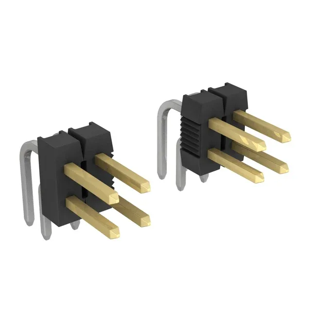
Board-Layout Fit: Pitch, Position Count, and Orientation
The 9-146308-0-17: The row spacing is also 0.100", so the footprint occupies a 0.100" x 0.100" square grid, which matches standard perf-board and prototyping layouts. This keeps the mated cable assembly low-profile against the PCB edge, saving z-height in enclosures where a vertical header would interfere with a cover or adjacent card.
Contact Interface and Cycle Life
Compare with tin-plated siblings in the same AMPMODU Mod II series: tin costs less but wears through in roughly 50–100 cycles and can frett in high-vibration environments. The 30 µinch gold layer here extends usable life well past 200 cycles, making it the better choice for test equipment, instrumentation, or any connector that gets unmated more than a few times.
Current, Temperature, and Flame Rating
In a 34-position header fully loaded, the total current through the connector is limited by the derating curve — at 105°C ambient, the per-contact current must be reduced to stay within the housing material's temperature rise ceiling.