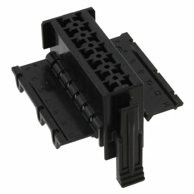
Housing for the Harness Side of a Junior Power Timer Connection
It accepts female socket contacts terminated to 20–24 AWG wire via crimp, then locks into the matching header — typically a TE 929500-series or equivalent pin header with the same 5.00 mm pitch and 2-row layout.
The 5.00 mm pitch and 0.220" (5.60 mm) row spacing give this housing a board footprint that matches the standard Junior Power Timer header layout — the same pitch used across the 2-, 3-, 4-, 6-, 8-, 10-, and 12-circuit siblings in the series, so the 14-position version simply extends the row length. The 2-row arrangement means the 14 circuits are split 7 per row, which keeps the connector width manageable for inline harness routing.
Contacts Not Included — Ordering the Full Connection
To complete the wire-side assembly, order the matching Junior Power Timer female crimp terminals separately. The standard terminal for this housing is the TE 929937-1 (tin-plated, 20–24 AWG) or 929937-2 (gold-plated, for higher mating-cycle duty). The crimp terminals insert into the housing cavities and lock with a positive retention lance; a secondary TPA (terminal position assurance) retainer can be added for vibration environments. The mating connector is a TE Junior Power Timer pin header — typically the 929500-series or 929504-series in a 14-circuit, 2-row, 5.00 mm pitch configuration. Don't order half a connection: the housing and terminals are separate line items on the BOM.