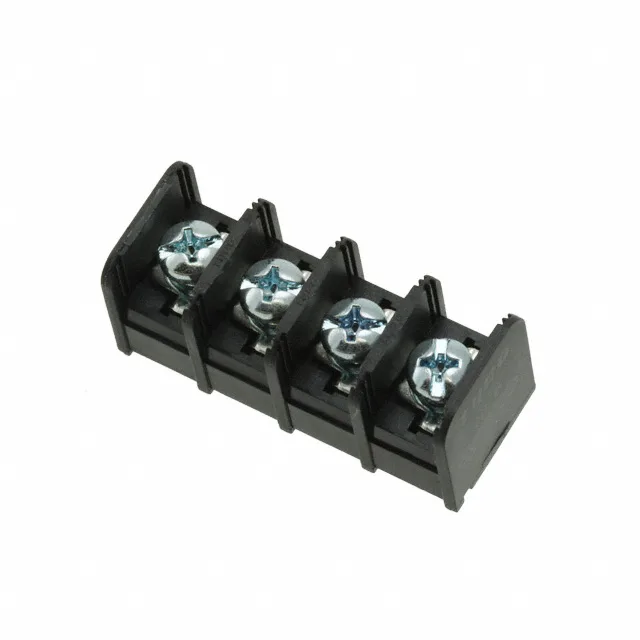
What this barrier strip does in the panel
It terminates up to 12-22 AWG wire under a screw clamp on the top side and routes the circuit through a PC pin on the bottom. The 0.375" (9.53mm) pitch gives each terminal enough room for a 12 AWG ring tongue without crowding the adjacent circuit — that spacing also supports the 300V rating across the dual-wall barriers. Rated 20A per circuit, this strip handles power distribution inside an industrial control cabinet or a power supply output stage where you need to land a heavy feed wire and take off several smaller loads.
Wire range and termination — what lands on the screw
The top termination is a screw clamp that accepts 12-22 AWG stranded or solid wire. The steel screw with zinc clear chromate finish gives enough torque to hold a 12 AWG conductor without stripping the head — the insulation is polyamide (nylon) rated UL94 V-0, so the housing won't propagate a flame if a short heats the terminal. Each of the 4 wire entries lines up with its own circuit; the dual-wall barrier between each position keeps a stray strand from bridging to the next screw.
Through-hole mounting and the board footprint
The 0.375" (9.53mm) pitch sets the hole spacing on the board layout; the single-row, 4-circuit arrangement keeps the footprint narrow. The nylon housing is black, so the strip stands out against a green FR4 board for visual inspection.