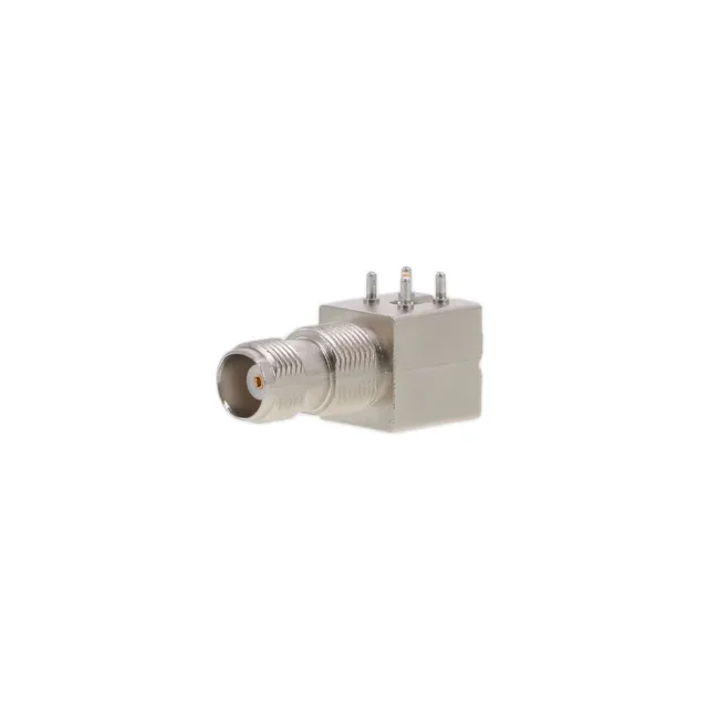
031-6294 — Amphenol product photo

Amphenol RF 031-6294 TNC Jack, 50 Ohm, 11 GHz, Bulkhead

MPN031-6294
Active

Amphenol RF TNC jack, female socket, 50 Ohm, 11 GHz, 500 V, panel mount through-hole right-angle, solder termination, gold-plated beryllium copper centre contact, nickel-plated zinc die cast body, bulk package.

$11.2200Ref. price · indicative, final on quote
StockContact for availability
MOQ1 pcs
  • New & original stockTraceable channels only — no mixed lots, no re-taped reels.
  • Factory packaging where availableSealed reels, trays and bags; cut quantities always stated on the quote.
  • Photo-verified countsEvery line counted and photographed before the box closes.
  • PayPal buyer protectionPay by T/T, PayPal or Payoneer — card payments covered end to end.

Specifications

031-6294 Technical Specifications
ParameterValue
Mounting typePanel Mount, Through Hole, Right Angle
Connector typeJack, Female Socket
Fastening typeThreaded
Voltage rating500 V
Frequency - max11 GHz
Mounting featureBulkhead - Front Side Nut
Operating temperature-40°C~155°C
Body materialZinc Die Cast
Housing colorSilver
Dielectric materialPolybutylene Terephthalate (PBT); Polytetrafluoroethylene (PTFE)
Center contact materialBeryllium Copper
PackageBulk
Impedance50Ohm
Body finishNickel
Mating cycles500
Insertion loss0.18dB
Number of ports1
Shield terminationSolder
Contact terminationSolder
Center contact platingGold

Product details

TNC Jack That Holds the Line to 11 GHz

What the 11 GHz and 0.18 dB Ratings Tell the RF Designer

The 11 GHz frequency ceiling is the defining spec on this jack — it is not a general-purpose signal connector. The 0.18 dB insertion loss at that frequency is a tight figure, meaning the impedance transition through the solder joint and the PTFE dielectric is controlled. The dielectric stack uses both PBT and PTFE; PTFE handles the RF path, PBT provides the structural support for the centre contact.

Mounting That Fixes the Jack to Both Panel and Board

The mounting combination is panel mount, through hole, right angle — the bulkhead front-side nut secures the jack to the panel face, while the right-angle solder tails route the signal perpendicular to the board edge. This footprint is common for RF jacks on the edge of a PCB that sits inside a shielded enclosure.

500 Mating Cycles and 500 V — What They Mean for Field Service

The 500 mating cycles is the standard for a threaded RF connector that gets disconnected a few times a year in the field — not a test-bench connector that sees daily swaps. The 500 V rating is high for a 50 Ohm RF jack; the creepage path is carried by the threaded interface, not the signal pin.

Frequently asked questions

What is the equivalent or replacement for 031-6294?

No official replacement is listed. The closest functional peer is the 031-6962, which shares the same TNC interface, 50 Ohm impedance, and 500 V rating, but uses a crimp shield termination for cable assembly rather than the solder shield termination on this panel-mount jack.

What is the insertion loss of 031-6294?

The insertion loss is 0.18 dB, measured at the rated frequency of 11 GHz.

What cable group is 031-6294 compatible with?

The 031-6294 is a panel-mount jack with solder shield termination — it is not designed for a specific cable group. It terminates directly to a PCB through its right-angle solder tails.