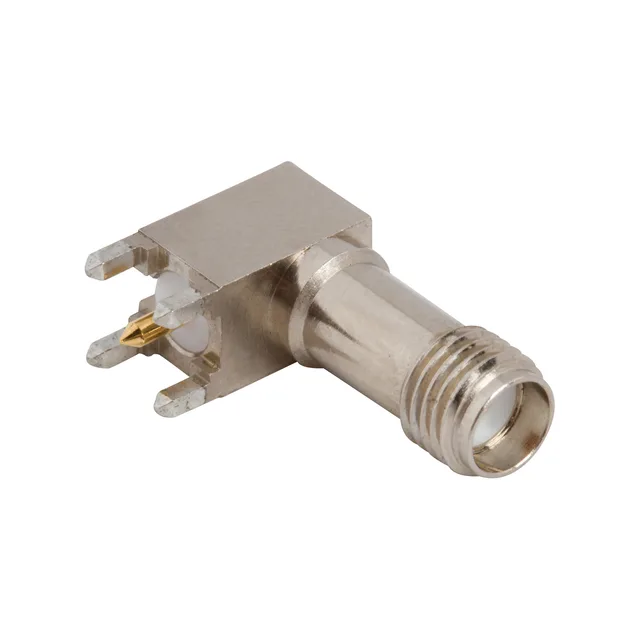
901-9917-3 — Amphenol product photo

Amphenol RF 901-9917-3 SMA Jack, 50 Ohm, 12.4 GHz

MPN901-9917-3
Active

Amphenol RF SMA jack, female socket, right-angle through-hole, 50 Ohm, 12.4 GHz, gold-plated beryllium copper centre contact, nickel-plated brass body, 500 mating cycles, 1 port, bulk.

$3.4300Ref. price · indicative, final on quote
StockIn Stock (18)
Lead timeIn Stock wk
MOQ1 pcs
  • New & original stockTraceable channels only — no mixed lots, no re-taped reels.
  • Factory packaging where availableSealed reels, trays and bags; cut quantities always stated on the quote.
  • Photo-verified countsEvery line counted and photographed before the box closes.
  • PayPal buyer protectionPay by T/T, PayPal or Payoneer — card payments covered end to end.

Specifications

901-9917-3 Technical Specifications
ParameterValue
Mounting typeThrough Hole, Right Angle
Connector typeJack, Female Socket
Fastening typeThreaded
Frequency - max12.4 GHz
Operating temperature-65°C~165°C
Body materialBrass
Housing colorSilver
Dielectric materialPolytetrafluoroethylene (PTFE)
Center contact materialBeryllium Copper
PackageBulk
Impedance50Ohm
Body finishNickel
Mating cycles500
Number of ports1
Shield terminationSolder
Contact terminationSolder
Center contact platingGold

Product details

SMA Jack for Board-Edge RF Launch

The Amphenol RF 901-9917-3 is a standard SMA jack — female socket, right-angle through-hole termination, 50 Ohm impedance. It is the board-mounted half of a threaded SMA interconnect, designed to mate with a male SMA plug (cable or bulkhead) using the standard 1/4-36 thread.

What the 12.4 GHz Ceiling Means for the Signal Path

The 12.4 GHz frequency rating is the upper end of the usable passband — beyond that, the VSWR and insertion loss rise above the SMA interface specification. For a 50 Ohm system running at 6 GHz or 10 GHz, this jack has headroom; at 18 GHz it does not. The limiting factor is not the centre contact geometry (beryllium copper with gold plating, good for high-cycle mating) but the dielectric and the right-angle launch transition through the PTFE insulator. The right-angle bend in the signal path adds a small inductive discontinuity that narrows the usable bandwidth compared to a straight-through SMA jack.

Mounting and Termination — Board Layout Notes

This is a right-angle through-hole part. The signal pin solders into the PCB, and the shield is terminated with solder to the ground plane — there is no crimp ferrule. The nickel-plated brass body provides the ground reference; the four ground legs (integral to the body) pass through the board and are soldered on the opposite side.

Frequently asked questions

What is the impedance of 901-9917-3?

50 Ohm nominal, which is the standard impedance for the SMA interface.