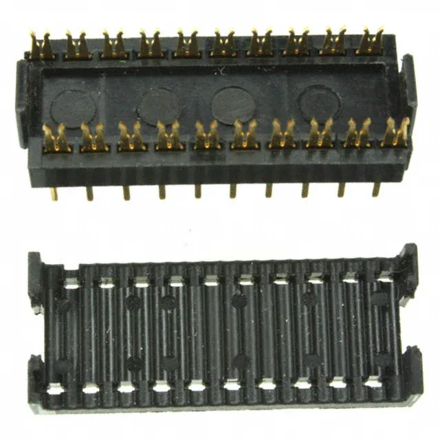
20-Position AMP-Latch DIP Header — IDC to Board Interface
The 1-746611-0: This dual-pitch architecture — 0.050" (1.27mm) on the cable side, 0.100" (2.54mm) on the board side — is the defining mechanical feature of the series: the tight cable pitch packs 20 circuits into a compact IDC termination, while the wider board pitch matches a standard DIP footprint for through-hole soldering. The header accepts 28 AWG stranded wire or 26-30 AWG solid wire, making it compatible with common flat ribbon cable stock.
Board-Side vs Cable-Side Pitch — Why the Two Numbers Matter
The 0.050" cable pitch, meanwhile, matches the standard 0.050" pitch of common 20-conductor ribbon cable. The 0.300" (7.62mm) row spacing is also standard for DIP packages. The feed-through feature allows the IDC termination to pass the ribbon cable straight through the header body, simplifying cable routing in daisy-chain or pass-through harness layouts.
Gold Plating Grade — 30.0µin for Reliable IDC Duty
This thickness provides good corrosion resistance in environments with moderate humidity or industrial atmospheres, and supports the multiple insertion cycles typical of IDC connector assembly and rework. For harnesses that may be disconnected and reconnected during equipment servicing, the gold-plated 1-746611-0 is the more durable choice.
Position Count Variants — 20 vs 16 Positions
Within the AMP-Latch series, the 1-746611-0 carries 20 positions loaded (all positions). The sibling 746611-6 is mechanically identical — same 0.100" board pitch, same 0.050" cable pitch, same 30.0µin gold plating — but with 16 positions. The board footprint and cable width scale with position count, so the 16-position variant occupies a shorter PCB pattern.