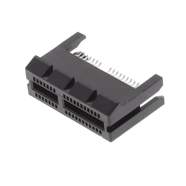
PCI Express Edge Connector for Board-Level Card Slots
A locking ramp on the connector body engages the card-edge notch to hold the card seated under vibration — a practical feature for industrial PCs or rack-mount servers where cards must not loosen during shipping or fan vibration. For a card slot that sees occasional swaps (a desktop motherboard or a test jig), this gold flash is adequate; for a hot-swap backplane with daily card changes, a heavier gold specification would be preferred.
Mounting and PCB Layout Fit
The straddle-mount footprint means the connector sits astride the board edge, with solder tails on both the top and bottom PCB surfaces. The card thickness it accepts is 0.062" (1.57mm) — the standard thickness for a PCIe add-in card. When laying out the board, the 1.00mm pitch sets the card-edge finger spacing; the connector's dual readout requires that both top and bottom pads on the card are aligned to the same pattern. The locking ramp adds a small clearance requirement on the card edge — the notch must be present or the ramp will not engage, and the card may not seat fully.