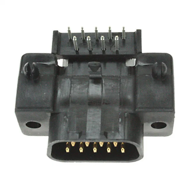
D-Sub Plug for a Standard DB-9 Footprint
It uses the standard DE (E) shell size — the common DB-9 layout — so it mates with any DE-size receptacle housing. Gold flash contacts on the mating side handle the signal duty for moderate-cycle applications — think test equipment, industrial controls, or serial data links where the connector sees occasional mate/unmate rather than daily field service. The brass contact material is standard for this class.
Board Locks Hold It Through Reflow and Vibration
This plug includes integral board locks — the two metal tabs that snap into the PCB and anchor the connector during wave soldering. On a right-angle D-Sub, the board locks take the shear force from cable strain and vibration that would otherwise work the solder joints loose. If you are populating a board that sees any mechanical shock, the board locks are the difference between a connection that stays and one that intermittents. The unthreaded housing/shell flange means the mating half provides the screw retention — the plug itself relies on the board locks and the friction of the D-Sub shell interface. For a fixed cable assembly that rarely unmates, that is fine. If the harness gets cycled often, pair it with a receptacle that has threaded inserts.
Sourcing and Lifecycle — Still in Production
Pinout and Wiring — What the DB-9 Layout Means
The 9 positions follow the standard D-Sub DE-9 pinout: two rows of 5 and 4 contacts. Pin 1 is at the top-left when viewed from the mating face (the wider row). The shell size (DE, E) guarantees the footprint matches any standard DB-9 receptacle.