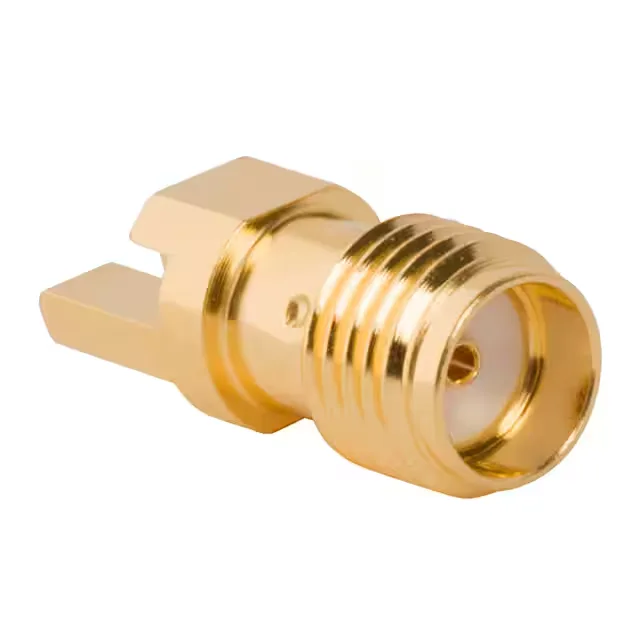
SMA Jack for Edge-Launch RF Paths
The 901-10513-3: It sits in the 901-10 series of precision SMA connectors, built for controlled-impedance signal paths up to 26.5 GHz.
What the 26.5 GHz Ceiling Means for Your Signal
Rated to 26.5 GHz maximum frequency, this SMA jack covers the full Ku-band and K-band without rolling off.
Board Edge End Launch — Footprint and Routing
The end launch mounting style places the connector at the PCB edge with the signal pin soldered directly to a microstrip or coplanar waveguide trace. The flange provides mechanical retention through the board edge cutout, and the shield termination is soldered to ground vias or a ground plane. This launch geometry keeps the signal path short — the centre pin transitions from the coaxial interface to the PCB trace within a few millimetres, minimising the inductance bump that a right-angle launch would add.
Comparing the 901-10 Siblings
The 901-10513-3 shares its 50 Ohm impedance, 26.5 GHz frequency ceiling, 500 mating cycles, and threaded fastening with the 901-10511-2 and 901-10511-3. The difference is in the mounting feature — all three carry a flange, but the 901-10513-3 is specified for board edge, end launch, while the 901-10511-2 and 901-10511-3 are listed with the same mounting type. For a buyer cross-referencing, the functional specs are identical; the choice comes down to packaging or supplier preference.